Frequency Electronics FE-73 Distribution Amp
Power Supply Rebuild

I picked this up on ebay back in early 2006. While it worked when I got it, it was very erratic. Output levels were all over the place and the power supply would shut down. It would be a pain in the neck getting is started again. I would have to plug and unplug it repeatedly (because there was no power switch) until it finally stayed up. I lived with this problem for 11 years. Reason was finding any information on this unit is like un-obtainum! I had no manual and I could find nothing on it. Everyone I asked knew nothing about it. In Oct 2017 I finally decided I was going to do something about it. Since I had no manual I manually traced the power supply and the 100KHz, 1MHz, 5MHz pre-amps. What I discovered was amazing, actually unbelievable. The power supply was not wired correctly - FROM THE FACTORY! Basically the pass transistors were shorted across by the wiring so there was no regulated supply to the modules. B+ was directly off the rectifier filter. I found other wiring issues as well. I will go into all these at the end of this page. But it led me to believe this is why I couldn't find anything on it. I believe there were lots of problems with this distribution amplifier and Frequency Electronics just plain abandoned it rather than fix it thus not many were made and there are almost none in circulation as a result of poor operation and limited manufacturing. I fixed this problem though and it is now a very good Distribution Amplifier that operates well.

My solution was to completely rip out the original power supply and build a new power supply using a modern day LM317K 3-terminal adjustable regulator.

Here's the existing power supply coming out. Hard wiring all over the place. It used mondo rectifiers and pass transistors which I don't understand. At first I thought they were big because the supply also charged the batteries but once I traced the circuit the power supply does not charge the battery. I measured load current flow at 500ma with an external power supply connected. So, with a rectified filtered voltage of 27v and a regulated output of 20v that put 7v at 500ma across the pass transistors which works out to 3.5 watts. It used three, now obsolete, PNP Silicon pass transistors. These were first introduced in 1957 by Texas Instruments as the first Silicon Diffused transistors. Each transistor was rated at 35watts so with 3 in parallel it was capable of 105watts. Way over kill. Kind of gives a date to when this Dist Amp was probably made though, I put it at late 50's early 60's. I would completely gut this old power supply and rebuild the new power supply in the same assembly.

     
Here it is going together. I discarded the old big lytic to give myself more room in the assembly. I reused the transformer but needed only one of the secondary's, the other was not used. First pic is everything in but the regulator board. The middle pic is the regulator board I built to replace the one that was in there. This board controls the LM317K and also has voltage dropping resistor for the front panel lamp which was a neon across the AC line and I replaced with a 345 10v lamp. The board also contains the dropping and adj resistor for the front panel meter. The last pic is the assembly with the reg board in it but not the transformer yet. Everything in and out of this assembly is through connectors so the assembly can be removed easily from the unit.

     
Here's some pics of it complete. Note that on the front panel I added a power switch and I replaced the neon lamp with a DC filament lamp. Middle pic is the back. I removed the old power cord crimp and replaced it with a traditional 3 prong socket which would enable me to pull the AC cord when removing it from the rack it's mounted in. In the last pic you see the connectors I used so that the whole power supply assembly could easily be removed from the unit. I also adjusted the value of the meter resistors in the pre-amp modules to get a correct meter reading on the front panel.  

   
Here's some front and rear views with it back in the Frequency Standard Rack. Works flawlessly now with consistent output levels

Here's the new power supply scat. It's a traditional 3-terminal adjustable regulator using the LM317K TO-3 package. It also includes the battery steering diode, note that is does not charge an external battery. If an external battery is used it will also need some type of charging mechanism to charge it. I'm not using an external battery but wanted to keep that capability. Also on the regulator board are the front panel lamp dropping resistor and the metering dropping resistor. I added the adjustable resistor in the metering line so I could adjust the meter for midscale indication.

The Old Original Power Supply

Here's the original old power supply I manually traced as I did not have a manual. At first glance it looks like a pretty conventional pass transistor type regulator. However, as I traced I found that the B+ terminal on the regulator board had two red wires on it. One went to the input of the pass transistors right off the rectifier/filter, I call this B++. The other red wire went to the output of the pass transistors regulated B+. Problem is this then shorts across the pass transistors through the B+ terminal on the regulator board. This is very clearly not right. And it appears it came from the factory this way, it did not look like anybody worked on it or made this change. So in reality there was no regulated B+, it was raw rectified/filtered voltage. I couldn't believe it. I retraced and retraced and ohm'd it and retraced again. This wiring was shorting the pass transistors. This was problem #1. So I removed the wire that went to B++. Now the power supply would not start up at all. Almost all pass transistor regulators need some type of start up scheme because when fist turned on there is not base-emitter bias on the pass transistors. Looking at the circuit it occurred to me the circuit off to the right of the pass transistors looked like a start up circuit but it was wired to the B+ output. But if it was connected to the B++ input it would initially bias the STC1800 device on which would turn the pass transistors on. I removed the B+ connection to this little circuit and connected it to the B++ input and sure enough the regulator now fired up when turned on. Again, it was wired like this from the factory. This was problem #2. It now had output but it was not adjustable. It was close to +20v but a little high. The regulator board looks to contain two regulation control circuits. One sense ckt, the right half, looks like it senses the B+ output which ultimately controls the pass transistor through the STC1800 device. Very traditional type sensing and control circuit in pass transistor regulators. The left half sense circuit though was/is a mystery. I'm not sure what it is supposed to be sensing to also control the pass transistor conduction. It has a negative voltage applied to it from a second winding on the power transformer and has B+ regulated voltage applied to it. I suspect, but did not try, that this little sense circuit should also be connected to the B++ input, not the B+ output. The STC1800 device is a mystery device to me. I tried doing some research on it and found a cross to an NTE186 NPN transistor. However, When I did a diode test on the device it did not look like a transistor at all. It could actually be an NPN transistor that was fried or it some type of device that was not an NPN transistor but some other type of obsolete device. Either way I was done screwing around with this old power supply and was the point I made the decision to just yank the old supply and build a more modern supply.

Additional Pics Of Circuitry I Traced


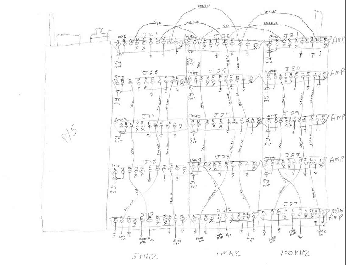
Wiring Detail

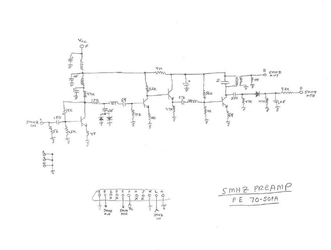
5MHz Preamp

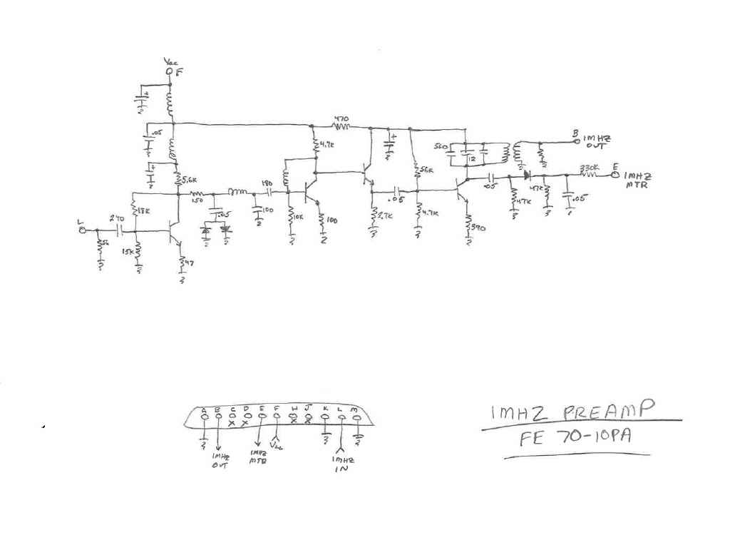
1MHz Preamp

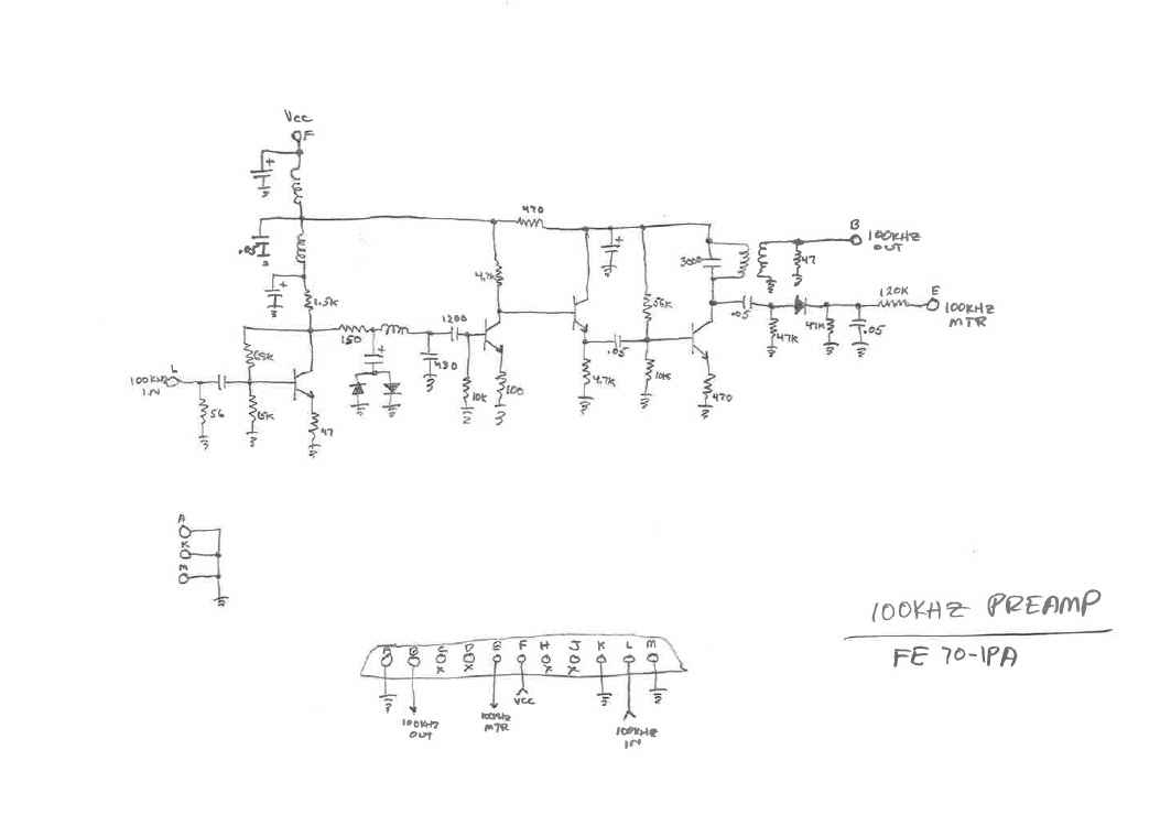
100KHz Preamp
Thought I would throw these in as well in case someone out there also has this unit and probably can't find anything on it either. I did not trace the PA modules. They were loaded with parts and I just couldn't bring myself to manually trace those circuits. I figure if I ever need to troubleshoot on of them, then I would trace them. 

Top of the Projects Page

Home