R-1051 Repair and Restoration
|
Picked this up early 2007 on eBay and finally got around to working on it recently. It's a straight R-1051, no suffix letter, with the 100 Hz only selectable between 000, 500, and Vernier. I first learned about this receiver while in the Navy in ETA Comm School Great Lakes back in 1977 and worked on them while in the Navy aboard the USS San Jose AFS-7 (1981-1984). This one was a little rough, looked as though it had been dropped and there is a dent in the rear where the Antenna connector is but it still seems to function. Problem is it had really crappy sensitivity and an incredible amount of noise on every frequency. Injecting a signal made no difference. It didn't matter how much signal I applied the noise level stayed there, it didn't quiet as signal level was increased. This is where I speculated the noise was probably coming from the synthesizer, which in the end proved to be a correct assumption. |
|
|
|
|
.jpg) |
|
|
| Despite my suspicion the problem was the synthesizer I started with the RF Amp just because I wanted to get into it anyway. Disassembly was easy and very straight forward, just follow the directions in the Repair of AN/WRC-1 and R-1051/URR 2N Modules publication NAVSHIPS 0967-034-2000. Above pictures show the assembly with the RF Strips removed. The ckt board showing in the 4th picture is not used in the receiver, this board is only used in the T-827 Exciter. The strips were very easy to remove. I checked continuities of the coils and the values and leakage for all the capacitors, all checked good on all strips. Next I cleaned up the contacts on the strips and then set them aside for reassembly and continued disassembly of the RF Deck. | |||
Alignment
| I did an alignment next and plotted a lot of data to reference how well alignment and fiddling was proceeding. I wanted to make sure I could actually see if what I was doing was for the better or the worse. In retrospect I probably should have fixed the synthesizer problem first so I could see the overall radio sensitivity as I progressed through this as well. Will remember that next time. As a result I was really only able to see performance from an RF block perspective rather than the entire radio perspective. Things worked out in the end though as I am getting 1uv sensitivities from the radio after all problems were fixed. Additionally, I didn't plot any performance data before I took it apart and refurbished/rebuilt it. So again I don't have that comparison. I did plot performance after it was rebuilt and before alignment, so that's my starting point. You can download the entire excel spreadsheet of data I plotted here, it may help as a reference if you tearing into your RF Amp. |
 |
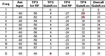
Plotting the Data I plotted the data in Excel and all the data is plotted the same way. My intent was to then take the data and make a graph so I could graphically view the gain/loss of; 1) the 1st RF, 2) the second RF, and 3) the overall gain/loss of the "box". Basically it's the long way of getting a swept view of the RF Amp. I set the spreadsheet up so all I had to do was enter the input signal level and the signal levels read at TP3 & 4 and formulas in the gain/loss cells would automatically calculate the appropriate gain/loss. To produce the graph I used the Freq column as the X axis and gain/loss as the Y axis on the graph. I also added a trend line to each plot to give an overall view for the plot. Each plotting of data produces three graphs, 1st RF, 2nd RF, and Overall. Here's the entire spreadsheet if you want to download it. R1051 RF Amp Perf Data I'm only going to show the graphs, not the raw data, in the following. |
Setting the Reference Point
| This first set of plots is the RF Amp Performance after I did the refurb/rebuild but before doing any aligning and fiddling with it. For this test I had the RF Amp in the radio, signal was injected at the antenna connector at -60dBm and outputs taken at TP3 & 4. I read the dB levels directly off the Spectrum Analyzer' screen. This was my reference for things getting either better or worse with playing. Keep in mind, none of these plots were to see what the smallest signal I can put in and still get a discernable output. The intent is to see how gain/loss changes. |
|
1st RF Output |
2nd RF Output |
Overall |
| Couple of observations on this first pass after refurb/rebuild. First RF Amp has a dip at 12 and 19 MHz. Overall gain of the 1st RF declines as frequency increases but overall the gain stays positive through out the range. 2nd RF gain stays level | ||
Performance
Still need to write this part up