Hallicrafters S-38 Shortwave

|
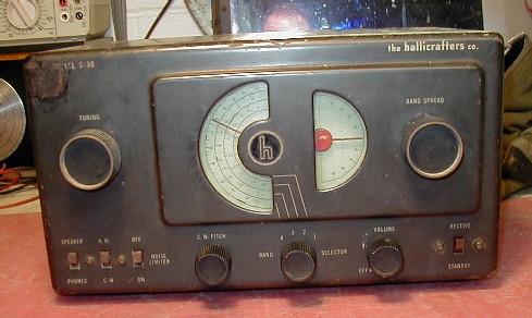
I had one of these receivers when I was a kid, it was the first Shortwave I had ever played with. My grandfather gave it to me one day when I was in his garage. I asked him what it was, he told me and then asked me if I wanted it, well of course I did! Did a lot of antenna experimentation and spent a lot of nights in the basement tuning in the world with that old radio he gave me. I went in the Navy and lost track of that old Hallicrafters receiver. Then when cruising the Internet one night I ran across some Hallicrafters pages and the spark rekindled my interest. I bought this one on eBay May 2002 just to relive my childhood. It's an original early S-38 with 6 tubes and the BFO pitch control. I had an A or B model when I was a kid as I had 5 tubes and didn't have the BFO pitch control on it. I decided from the first day I received it I was going to tear it down and completely rebuild it. I don't know if it worked when I received it. Supposedly it worked according to the seller but I was unable test it as I had my son (teenager) checking the tubes for me and in my absence he fried the filaments on two tubes. He was turning up the heater voltage watching it glow brighter and brighter until poof. He thought it was so cool he did another one! I couldn't find it in myself to get on him about it to much as I did the same thing in my early learning stages as a kid. Of course I did take advantage of the situation and educate him a little on tubes. Visually the condition: - The outer case was a little rusted in spots. - The paint is chipped off the upper left hand corner of the case and black marker was used to color it in (I believe the seller did it for the eBay photos). - Both the main and bandspread tuning was not smooth, it was very erratic, the dial cord obviously needs a little work. - The bandspread pointer had fallen off in shipping but went snuggly back on. - All covers where present but the back cardboard cover was broken in two but very carefully assembled so it looked in tact. - Component side of the chassis had a lot of melted wax all over the place, looked like all the old paper caps had melted wax all over the place. - Seller claimed to of had it repaired and it showed! Hope the seller doesn't use that repair shop a lot because it was really crappy work. As an example the power supply cap was just laying loose in the chassis. Looked like he tried to solder it down to the chassis but had a rosin connection which broke loose, obviously no concept of a HOT iron for chassis work. - And in general just dirty all over, inside and out. |
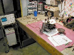
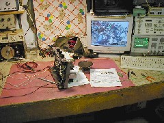
| I completely stripped the chassis down to a bare chassis. Drilled out all the rivets and removed everything. The rubber grommets used to insulate the chasses from the case were in bad shape and will be replaced as well. I wire brushed the chassis to remove all the oxidation and grime. and then started reassembly. I was able to remove the bandspread bushing, remove the ball bearing stuck in there, and reassemble it. There is a slight amount of play in the shaft but it works great now. I didn't take the rust off the tuning cap as I didn't want to screw it up. I did clean it as best possible and lubed the bearings and bushings, I'm sure it will probably be okay. There is no rust or corrosion on the plates so I'm probably okay. |
|
Some Assembly Shots |
|||
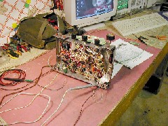
| Here it is about half way. As you can see the chassis is all wire brushed and shiny now. I did remove everything, I had to nut and bolt everything back down after drilling out the rivets. I mounted the tube sockets from the top of the chassis rather than from underneath as was originally done from the factory. No particular reason why, mostly I just liked the way it looked better having the socket mount rings on the top of the chassis. I replaced the power cord with a polarized 3 prong plug. I will connect the green safety ground wire to the cabinet case when it's installed. I noticed the Osc padder cap had a crack in the porcelain all the way across it but I think it will be okay. I replaced all the resistors and caps with the exception of two Mica caps. I also did some wire rerouting from the original and added a couple additional RF bypass caps in spots I thought it might help out. I busted the speaker socket drilling out the rivets and so replaced it with an RCA phono jack. I noticed that the IF transformers had different part numbers and were switched in the way the were actually mounted according to the parts list and schematic. I switched them back even though it probably makes no difference. In the mean time I bought a complete new set of NOS tubes. |
|
Rebuild Complete Well the Chassis part anyway. Still have to do the case. |
|
Here's the completed chassis rebuild showing the Osc and Mixer components installed. I used solid center conductor RG58 for all the coil wiring. The new tubes are installed. Restringing the dial cord was a breeze, it went much easier than I had anticipated. The play in the Bandspread is hardly noticeable at all. I repainted the red dial pointers and just washed up the green dial plate. It looks beautiful and I'm very excited about trying it out and seeing how it works. Alignment is next. |
 |
 |
 |
| Alignment | ||
| Alignment was pretty straight forward and it was WAY out of alignment. The only thing I could just barely receive before alignment was WKRS 1220 located right here in Waukegan. It aligned up very nicely. The only slight problem I had was with the Osc padders. The entire padder cap has a hairline crack running through it and you can tell when trying to adjust it. It was very difficult to get it tuned with the crack but with patience I was able to get it set. Once aligned I was able to get most BCB stations and even an Indiana and Canadian station around 9Mhz, in my basement, with just a little adhock vertical and no ground! I was getting pretty excited. Next I need to do the case and put up a long wire antenna. One thing I did notice during alignment was that when not using an isolation transformer the tubes would start lighting up when I connected the test equipment grounds, even with the unit turned off. This makes sense since it is the return side of the line that gets switched with the on-off switch. In retrospect, if I ever do another one of these AC/DC models I will change the switch to the hot side of the AC line. This one is staying the way it is. |
Some Before - After Comparisons