%20Small.jpg)
Frequency Standard Rack
%20Small.jpg)
| I originally built this in 2013 but it finally became complete as I originally envisioned it to be in Jan 2018. This is my shop frequency standard that provides a reference frequency for all my test equipment that accepts an external standard. My inspiration for this project was my compulsive obsession with frequency accuracy. I have this need to feel assured that when I read or generate a frequency with my test equipment I know the frequency is spot on. I have even been known to add an external reference to pieces that only have an internal reference. Following are the major components of the rack. |
|
|
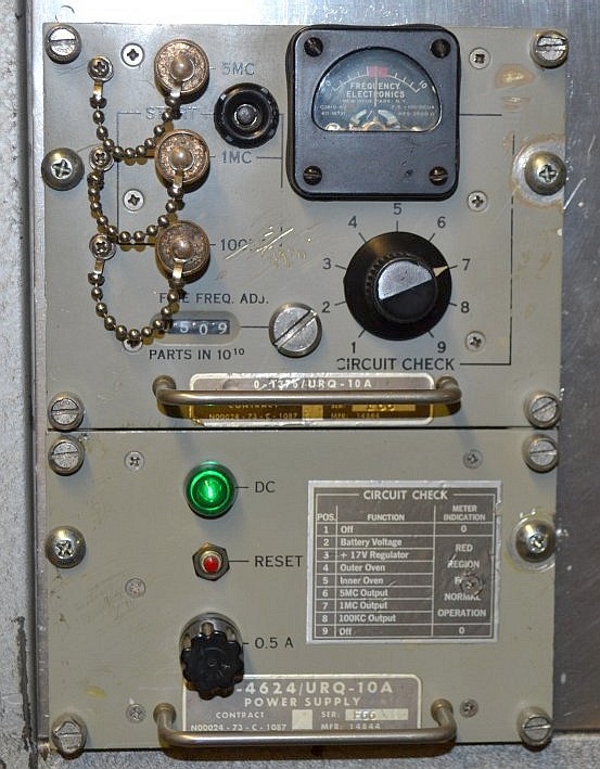 AN/URQ-10A
Frequency Standard AN/URQ-10A
Frequency StandardThis is the heart of the system. Had these on the ship when I was on in Navy (USS San Jose AFS-7) and when I saw one show up on e-bay back in early 2003 I had to have it. It's a highly stable crystal oscillator that produces outputs of 5MHz, 1MHz, and 100KHz. The 5MHz oscillator is contained in a double oven arrangement with an inner and outer oven. It comes with an internal battery for back up but the battery in mine is shot and is now un-obtainum. It has provision for an external battery but I ended up going with the option of a UPS on the AC supply line. The UPS only backs up the this unit, not the entire rack. I never turn this off to maintain stability of the oscillator. It has outputs on the front panel and the back panel. This standard has proven to be rock solid. I fine adjusted it once against WWV and have not needed to adjust it since. |
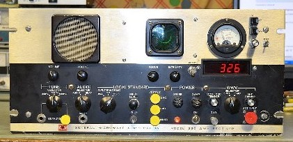 General
Microwave 550 WWV Receiver General
Microwave 550 WWV ReceiverThis unit enables me to align the URQ-10 Freq Standard to NIST Standard by comparing the Frequency Standard to the broadcast WWV signal. Once the URQ-10 is matched to WWV the URQ-10 is now aligned to NIST standard. This suites my complusive obsession just fine as I now know the frequencies from the rack are spot on. I picked this unit up on ebay in late 2003. It was a work in progress for many years. It had ugly holes cut in the front panel by the orginal owner who was going to add a clock to it. It has been a project of mine a couple times. See General Microwave 550 WWV Rcvr and Adding a Digital Clock and IF Xtals to the WWV Receiver. I recently completed the addition of a clock to the unit to fill the ugly holes and after 15 years of searching I finally came across an IF crystal pair which gives the unit a BW of 50Hz for comparing the standard to the WWV signal. Basically I adjust the URQ-10A for a non rotating half moon on the WWV display. Clockwise rotation of the half moon means the standard is to high and counter clockwise rotation means the standard is to low in frequency. Adjusting the fine adjust on the URQ-10A for zero rotation means the URQ-10A is exactly aligned to the WWV signal. The Frequency Standard Rack is now spot on to NIST Standard. |
 Frequency
Electronics FE-73A Distribution Amplifier Frequency
Electronics FE-73A Distribution AmplifierThis unit takes the 5MHz, 1MHZ, and 100KHz from the URQ-10A and provides three 5MHz, six 1MHz, and three 100KHz outputs for distribution. Picked this up on ebay back in early 2006. It seemed a perfect match for the URQ-10A. While it basically worked when I got it there were numerous erratic problems with it. I recently fixed it for good in Oct 2017, see project Frequency Electronics FE-73A Distribution Amplifier. |
 Home
Brew 10MHz Doubler-Distribution Amp Home
Brew 10MHz Doubler-Distribution AmpThe one problem I had was that I didn't have a 10MHz reference that a lot of HP and other test equipment require. In 2012 I solved this problem by building a unit the doubled the 5MHz to 10MHz, amplified it, and then distributed it to six 10MHz outputs. See project Home Brew 10MHz Doubler Distribution Amp. |
.jpg) Bottom Panel
Bottom PanelI needed a bottom panel because the URQ-10A would have left a huge empty void. It was a lot of space to cover so I had to figure out what I was going to do with all the space. There are outputs for all the rack frequencies on the front panel but they're at to high a level to use for anything if I wanted to tap into them for testing or R&D. So I added a really nice JFW 50DR series 0-110db 1db per step attneutator with input and output jacks on the front panel. But that still didn't cover much blank space so I reverted to overkill. Meters, knobs, lights, switches, etc are always cool. I put a main breaker on the panel. I added AC line voltage and current meters to monitor rack AC Supply. Left meter is the AC amp meter, 3A full scale. Right meter is the AC Voltmeter that is selectable to read the AC Line or the UPS AC out. And of course I had to add lights that indicate AC Line in and UPS line out. %20Small.jpg) Here's
a peak behind the panel with the WWV Receiver removed. URQ-10A is on the
left. The UPS that backs up the URQ-10A only is on the right side. It's
a
Tripp Lite ECO650LCD I picked up at Walmart. Grey project box in the
center rear is a pad I built to go between the URQ-10A outputs and the
FE-73A Dist Amp but in the end I did not use it and just left it in
there. To the right of the pad is the AC line imput sub-chassis that
contains the line filter and provides routing connections of the AC for
the rack. Here's
a peak behind the panel with the WWV Receiver removed. URQ-10A is on the
left. The UPS that backs up the URQ-10A only is on the right side. It's
a
Tripp Lite ECO650LCD I picked up at Walmart. Grey project box in the
center rear is a pad I built to go between the URQ-10A outputs and the
FE-73A Dist Amp but in the end I did not use it and just left it in
there. To the right of the pad is the AC line imput sub-chassis that
contains the line filter and provides routing connections of the AC for
the rack. |
|
|
 |
 |
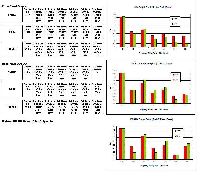 |
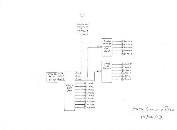
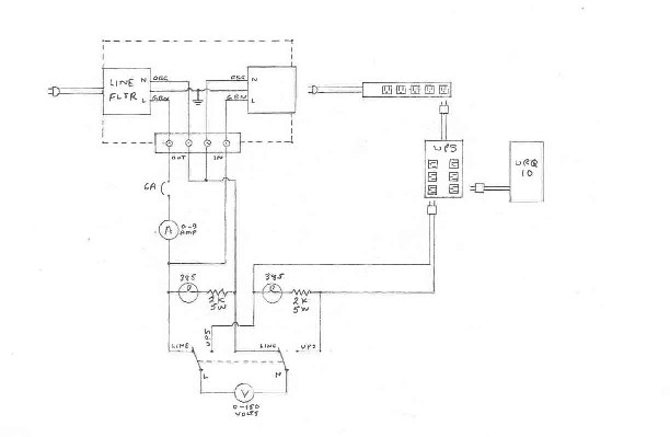
| Here's some misc stuff. First pic is a block diagram of the Frequency Standard Rack. Second pic is the AC line distribution scat. Last pic shows the outputs from the rack. It shows the URQ-10A output and harmonic levels on the front and rear at the output jacks. This is a screen capture of the first tab of an excel sheet. You can download the entire spreadsheet which also shows the output levels of the FE-73A and the 10MHz Doubler Distribution Amp on additional tabs at the bottom of the spreadsheet. | ||
|
|
|
%20Small.jpg) |
%20Small.jpg) |
| Here's some front and rear views of the completed Frequency Standard Rack. | |
|
|
|