My Inverter


I started on this project summer of 1998. My inspiration for this project is linked to the poor power grid my house happens to be on.  Every Spring we loose electricity numerous times during storms.  I wanted to have a power source that would automatically come on line and power select devices when power was lost.  This project was the answer.  I wired the inverter right into the existing electrical system of my house.  When power is lost the inverter automatically kicks in and powers up my video distribution board in the basement, an outlet in the front room with the phone and one lamp plugged into it, another outlet in the front room for general use, and finally the outlet the TV is plugged into. I spent approximately 5 months designing, bread boarding, testing, building, testing again, and modifying the unit before coming up with the final product.

When power goes out, within 2 minutes the inverter kicks in and the front room light comes back on, the TV comes back on, the phone is active again, and I have an outlet available to plug in a fan (or anything else) on those warm spring nights.  I'm the envy of the block.  While all the other houses are black my living room is lit up and I'm continuing to watch TV.

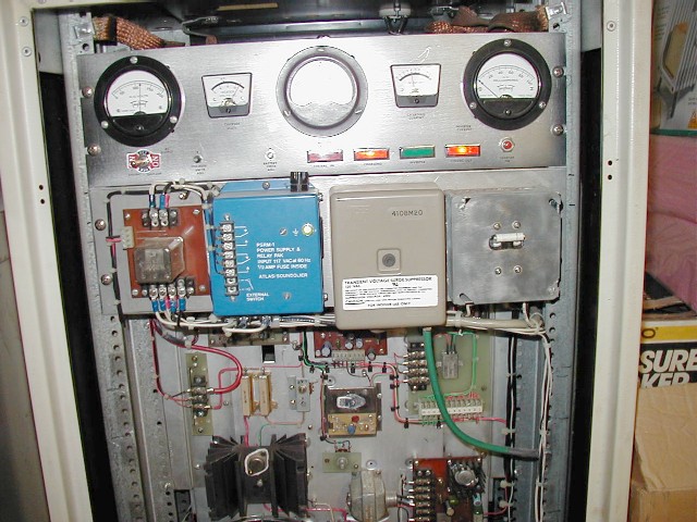
The picture to the left is the finished product sitting in my basement.  Basically it converts the power from two, parallel connected, marine deep cycle, 12-volt batteries to 115vac powering my outlets. I designed the unit to supply a maximum load of 500 watts at 115vac for up to 4 hours.  Typical load is approximately 382 watts which it can sustain for 5 to 6 hours depending on the charge of the battery at the time power was lost. When the inverter is in operation at the typical load of 382 watts, approximately 50amps is drawn from the batteries.  That equates to an efficiency of about 55%, the best I could eek out of it.  I chose marine deep cycle batteries because of there ability to provide sustained high current levels over long periods of time.  The only real money I put into the project was the purchase of the batteries, pretty much everything else I had on hand.

When Comm Ed gets it together and finally restores powers the inverter stays on line for another 5 minutes before seamlessly switching back over to commercial power. I allowed for the 5 minutes to ensure commercial power was stabilized before taking the inverter back off line.

I designed battery charging to be fully automated.  I designed sense circuits that automatically start battery charging when battery charge drops to approximately 90% of charge. This ensures the batteries are always maintained to at least 90% of full charge.  Charging is automatically controlled to charge at a maximum of 8amps and slowly reduce to a trickle charge as the battery approaches 100% charge.  I chose this charge method to maximize battery charge/discharge cycle lifetime.  Battery charging then automatically shuts down when 100% charge is obtained.  I also designed in low battery sensing so that in the event power is lost for a prolonged period of time the batteries will not be discharged to a point that will permanently damage the lead-acid batteries.  Whenever power is restored the charge cycle is always immediately activated no matter how short a period the power may have been out.  The charging circuitry then takes over to control the charge as appropriate. Here's a couple more pics:

Meter Panel and AC Distribution Panel. Meters show AC Input, Charge Voltage, Battery Voltage, Charge Current, & Inverter Current draw Respectively. Center chassis has all the timing, control, and charger circuitry on it. I designed all the circuits and even etched all the circuit boards. Bottom chassis is the actual inverter circuitry. See all the big heat sinks and transformers? Heat and core eddy currents is the where most of the other 45% of efficiency is wasted.

And what engineering project would be complete without documentation. Yes, I even put together a tech manual.  Interested in the fine details? You'll need Acrobat reader, documents are in pdf format, here they are:

I.) System Description

- System Functional Block

- System Diagram Front View

- System Diagram Rear View

II.) Timing Control

- Timing Control Schematic

- Timer-Low Battery Disconnect PCB

III.) Low Battery Disconnect

- Low Battery Disconnect Schematic

IV.) 115VAC Source Switch

- 115VAC Source Switch Schematic

- 115VAC Source Switch Control PCB

- 115VAC Source Switch Relay PCB

V.) 9.6volt Regulator

- 9.6volt Regulator Schematic

- 9.6volt Regulator PCB

VI.) Charger

- Charger Schematic

- Charger Turn-On Control Schematic

- Charger PCB

- Charger Regulator Assy

VII.) Timer Line Sense Module

- Timer Line Sense Module Schematic

- Timer Line Sense Module PCB

- Timer Line Sense Mod

VIII.) Battery Fuse-Filter Assy

- Battery Fuse-Filter Assy Schematic

- Battery Fuse-Filter Assy PCB

IX.) Power Supply Assy

X.) Inverter

- Inverter Schematic

- Inverter PWM IC

- Inverter PCB

- Inverter Chassis

XI.) Current Meter Shunt Assy's


XII.) Front Panel

- Front Panel Rear

XIII.) Relay Panel

- Main Relay Detail

- Charge Relay Detail

XIV.) Interconnect Wiring

- AC Wiring Detail

- Timer Low Battery Disconnect PCB Wiring Detail

- 115VAC Source Switch Control PCB Wiring Detail

- 115VAC Source Switch Relay PCB Wiring Detail

- 9.6 Volt Regulator Wiring Detail

- Charger PCB Wiring Detail

- Timer Line Sense Module Wiring Detail

- Battery Fuse-Filter Assy PCB Wiring Detail

- Power Supply Wiring Detail

- Inverter PCB Wiring Detail

- Battery 12 Volt Wiring Detail

- Control Chassis Wiring Detail

- Inverter Chassis Wiring Detail

XV.) Maintenance

- Control Chassis Adjustments Location

- Power Supply Adjustments Location

- Charge Voltage Level Set

- Low Battery Charge Level Set

- Front Panel Charge Voltage meter Calibration

- 9.6 Volt Regulator Level Set

- Low Battery Disconnect Level Set

- Inverter Line Frequency Adjustment


Top Of Projects Page


Home